Map My World Robot

Abstract

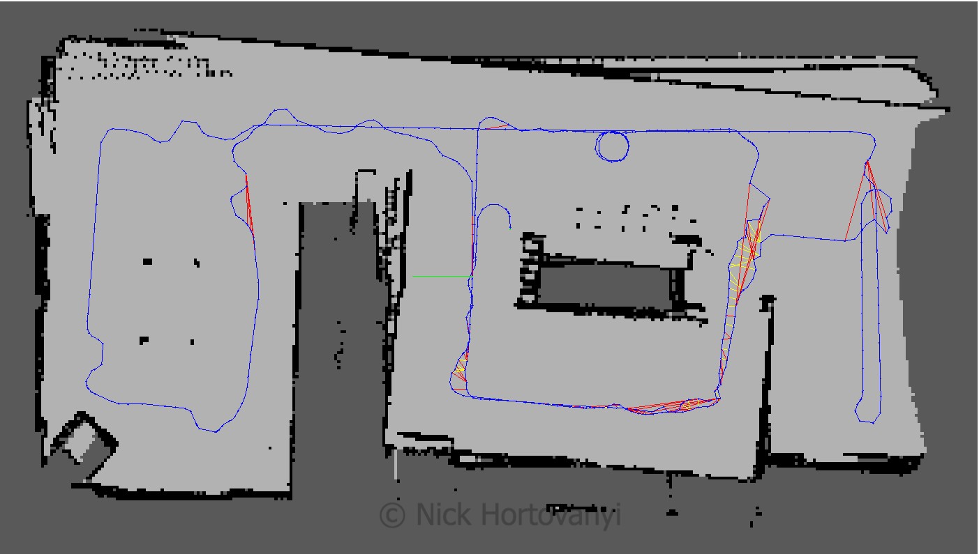
The third project in term 2 of the Udacity Robotics Nano Degree program requires students to use ROS and Gazebo along with RTAB-Map, to create a 2D occupancy grid and a 3D octomap of two environments – one supplied and the other student created.

Students extend a previous robot creation to upgrade sensors to supply the necessary sensor messages for RTAB-Map. This leverages the laser scanner, IMU/Wheel Encoder but replaces the camera with a RGB-D camera (ie kinect).

Further the ROS project is created with all links connected with appropriate naming and mapping.

The robot is launched and teleoped around the room to generate a map of the environment.

After successfully mapping the supplied environment, a student defined environment is created and mapped using the same technique.

Introduction

In this project a robot model uses a Simultaneous Localisation and Mapping (SLAM) technique called RTAB-Map (Real-Time Appearance-Based Mapping). It is a RGB-D Graph Based SLAM approach that uses incremental appearance based loop closure detection.

The RTAB-Map ROS wrapper is leveraged with visual representation in real time via rtabmapviz. The resultant map is stored in local database that be later interrogated via rtabmap-databaseViewer.

Background

When a robot encounters a new environment where there is no supplied map, it needs to be able to create this map and localise its pose using it. This combined localisation and mapping process is referred to as SLAM (Simultaneous Localisation and Mapping).

The main mapping algorithms are Occupancy Grid Mapping, Grid-based FastSLAM, Graph-SLAM and RTAB-Map.

The Occupancy Grid Mapping is a 2D algorithm where each grid cell is identified as Unknown/Undiscovered Zone, Free Zone or Occupied. This represents a slice of the 3D world.

The Grid-Based FastSLAM approach combines SLAM (Synchronised Location and Mapping) using a MCL (Monte Carlo Localisation) Algorithm and an Occupancy Grid Mapping. The main advantage of is the MCL particle filter approach but it always assumes there are known landmark positions. Thus it is unable to model an arbitrary environment.

Graph-SLAM uses a graph based approach to represent poses, features from the environment, motion constraints (between two poses) and measurement constraints (ties together a feature and a pose). It solves the full SLAM problem, it covers the entire path and map and not the most recent pose.

This project uses RTAB-Map, which is a Graph-SLAM approach that uses loop closure with Visual Bag-of-Words for optimisation.

The loop closure detection occurs against working memory to constrain the number of images interrogated. Working memory can be transferred and retrieved from long term memory to reduce complexity. The algorithm used for loop closure detection is SURF (Speeded Up Robust Features).

The possible outputs of RTAB-Map are 2D occupancy grid map, 3D octomap or a 3D point cloud.

Robots are of varying dimensions inclusive of height. Whilst mapping a 2d environment may show where fixed walls etc are it does not take into account height. A robot, that is propelled on the floor, may be able to navigate under some obstacles but not others eg a chair vs a large table. Hence the need to understand the environment from a 3D perspective.

However building a 3D map is more costly then a 2D map. This is not only in terms of Compute & Data costs but also in the cost of the sensors required. However, simple sensors such as a single camera may be cheaper but the algorithms required can be more complex.

Robot Model Configuration

The robot model used was based on the nick_bot created in the previous project as the student robot model (which had a square base with two actuators for the left and right wheels). The camera was removed and replaced with a kinect leveraging the openni_camera ros package with the gazebo controller Openni Kinect.

No changes were made to the hokuyo laser range finder.

An additional joint was added to rotate the kinect data 180%. It was positioned on the front of the robot so as to not interfere with the laser range finder.

The nick_bot configuration files can be found under the urdf directory.

Visualization of the frames follows
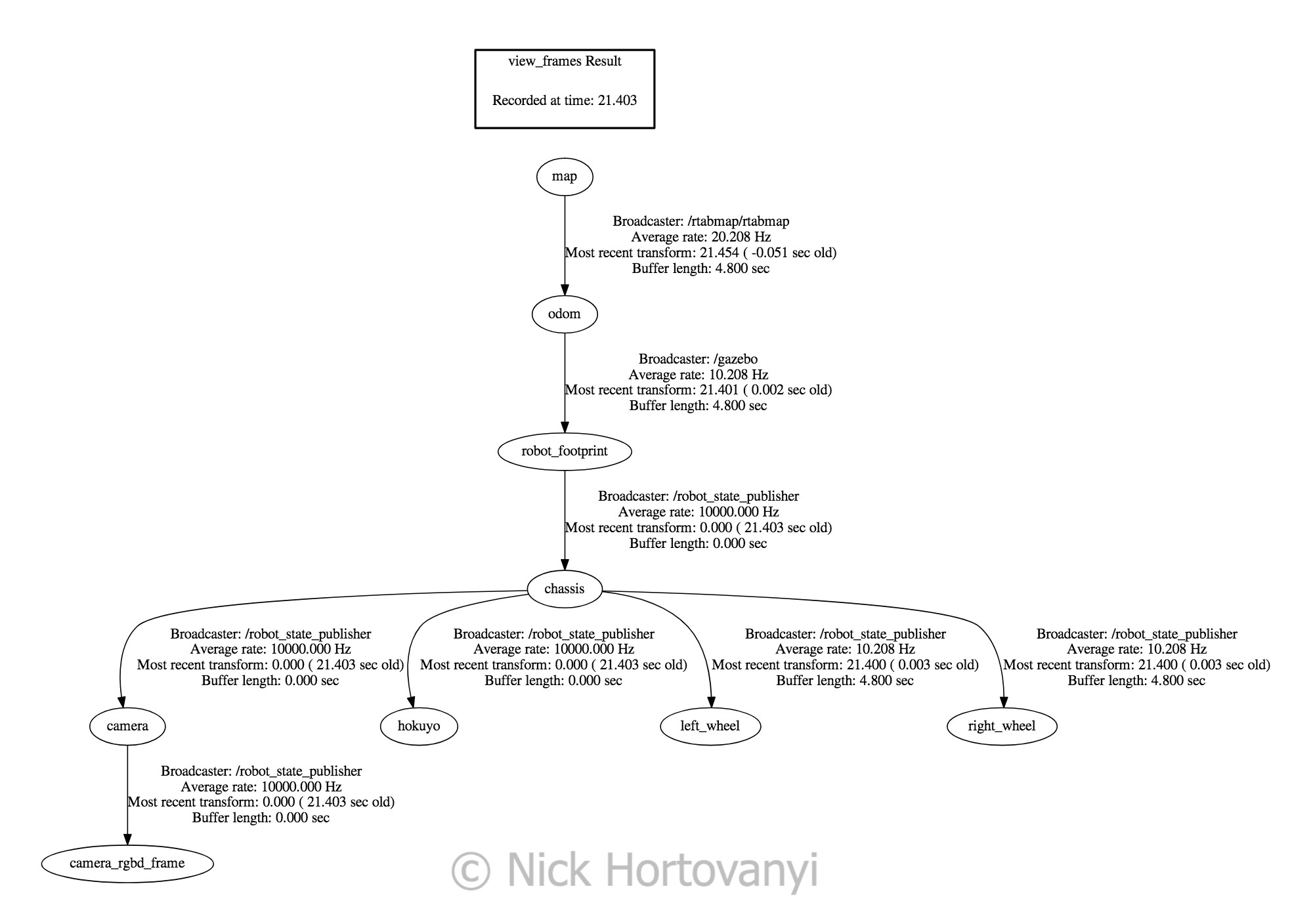
frames.png
frames.png

World Creation

Two worlds were created in gazebo – one supplied as kitchen_dining.world and the other student customised nicks_building.world
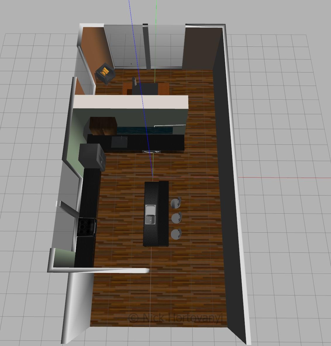
kitchen_dining.world
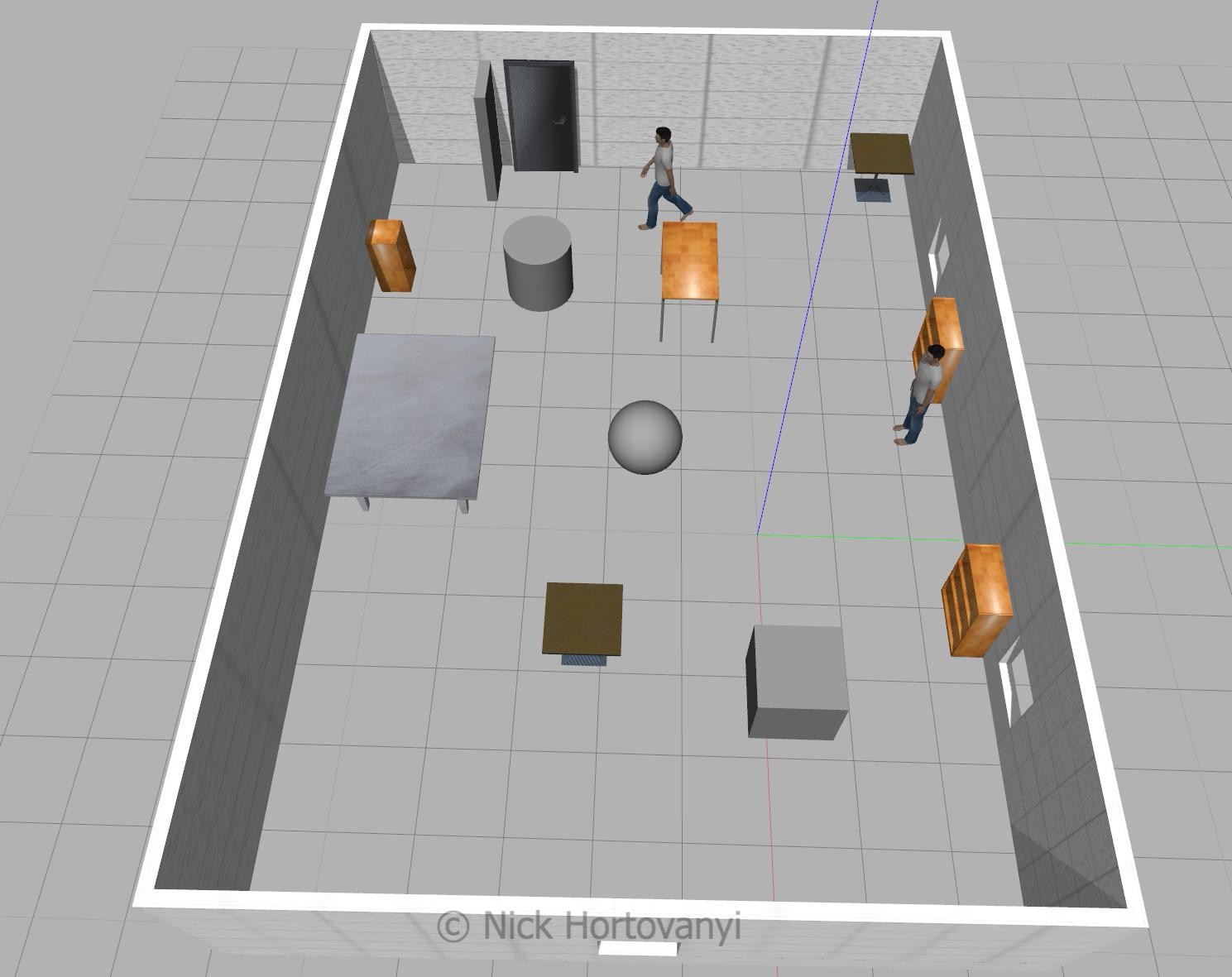
nicks_building.world

Fixtures were selected in nicks_building.world to give sufficient points for the SLUR algorithm to detect distinct points. Items were also placed to ensure that the features could not be mistakenly detected twice ie a person was placed next to one of the bookshelves. Sufficient space was left for the robot to navigate.

The following tree diagram depicts the package structure and files that made it up.

├── CMakeLists.txt
├── launch
│   ├── config
│   │   └── robot_slam.rviz
│   ├── mapping.launch
│   ├── robot_description.launch
│   ├── rviz.launch
│   ├── teleop.launch
│   └── world.launch
├── materials
│   └── textures
│       └── kinect.png
├── meshes
│   ├── hokuyo.dae
│   └── kinect.dae
├── output
│   └── rtabmap.db
├── package.xml
├── README.md
├── rtab_run
├── teleop
├── urdf
│   ├── nick_bot.gazebo
│   └── nick_bot.xacro
└── worlds
    ├── kitchen_dining.world
    └── nicks_building.world

This tree structure was chosen based on the previous student project that conformed to known gazebo/ros standards with the addition of an output directory to store Udacity project writeup requirements.

Results

kitchen_dining_3d
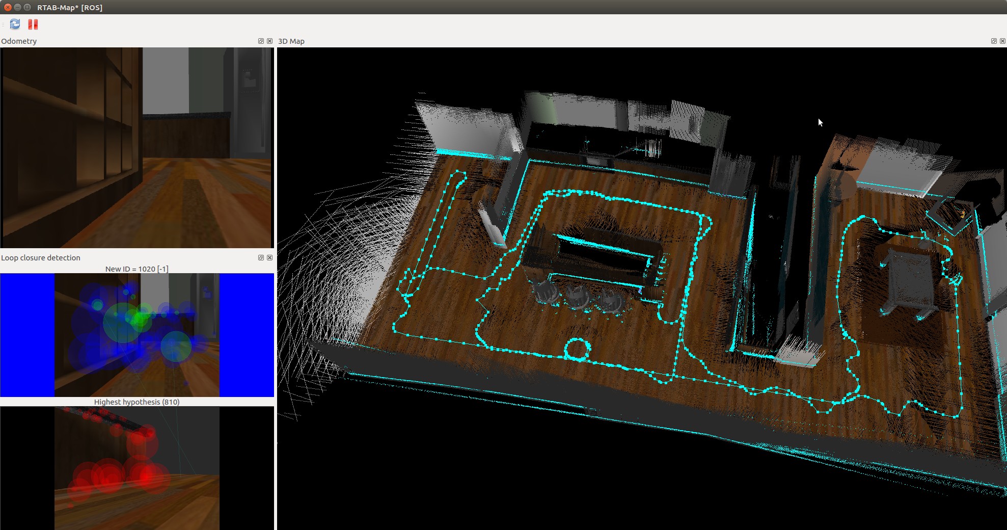
kitchen_dining_3d

kitchen_dining_2d

kitchen_dining_2d

nicks_building_3d
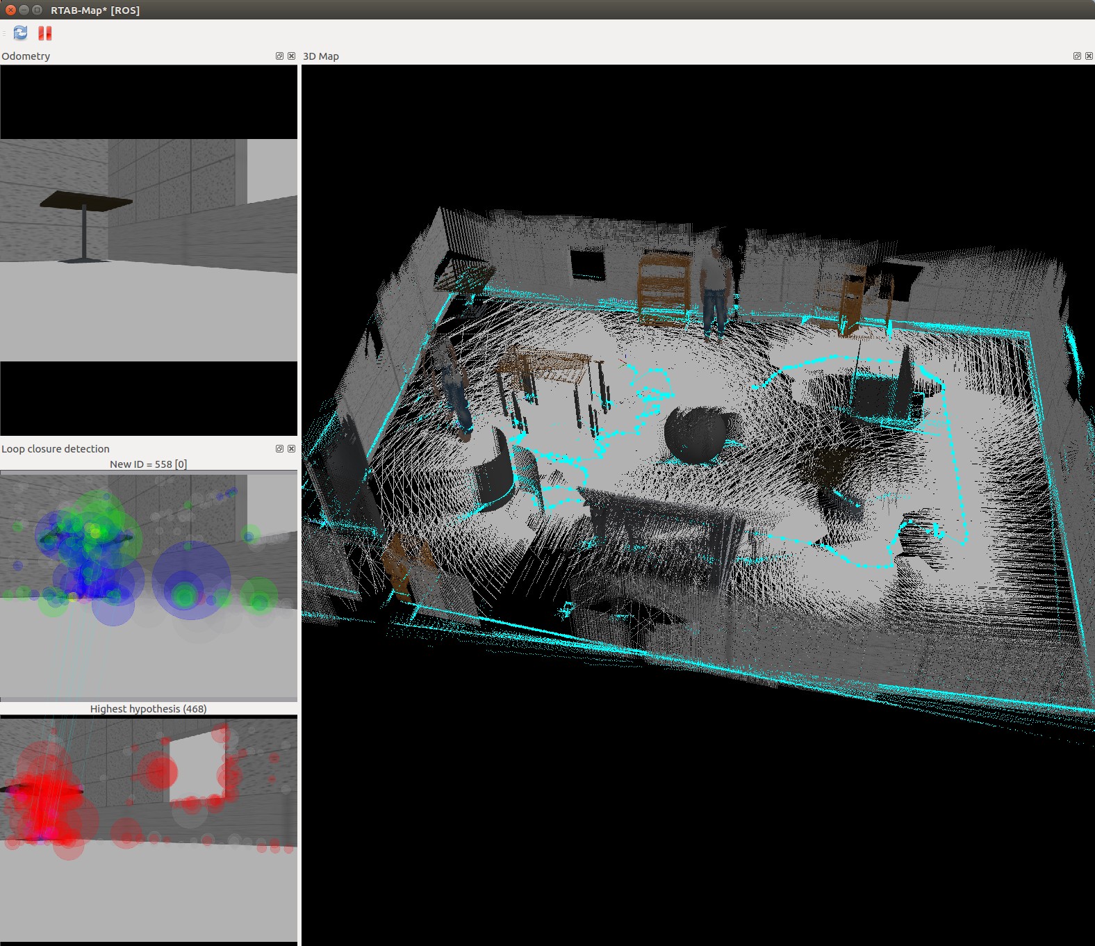
nicks_building_3d

nicks_building_2d
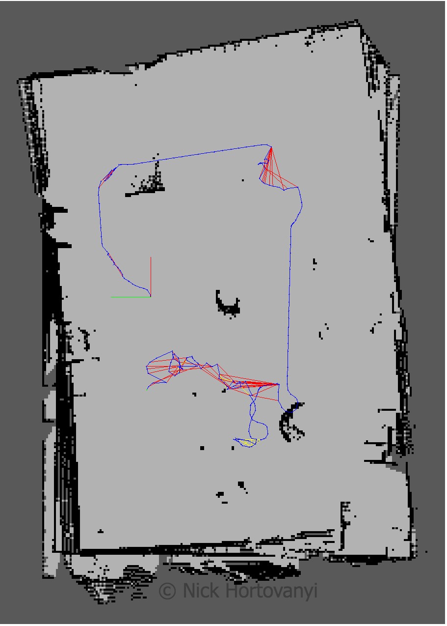
nicks_building_2d

Discusion

The robot was teleoped (navigated via the keyboard) around the room. At some points the robot did not move forward. This appeared to be when it started to perform loop closure. Kp/MaxFeatures was halved to 200 and Vis/MinInliers was reduced from 15 to 10.

However the 3D map quickly started to resemble the physical kitchen dining gazebo model. To improve loop detection rates some, on the spot circles were performed. Of particular note were the features in the main kitchen area. More SURF features were identified there as there was more variation in the surface s.

The nick building gazebo model wall surfaces were tiled, repeatable pattern with lack of other discerning features sometimes caused the loop closure detection to map to an incorrect previous image. This then distorted the map. Additional features were added to achieve a successful map.

The kitchen_dining model performed significantly better then the student created nicks_building model. This was due to the richer and more complex features of the kitchen_dining model.

Future Work

Mapping is important to help understand the world. There are a plethora of sensors and of interest is the about to arrive solid state lidars. As the price point of these sensors continues to drop it will open up opportunities to create richer and more realistic 3D maps at a cheaper price point.

Being able to map an environment cost effectively to create a replicated virtual world will increasingly be important to allow for the training of deep learning models. We are actively looking to do this and then supplant the trained model back into a robot so it can navigate in the original environment that was mapped.
Where am I

Where am I? Project Writeup

Abstract

The second project in term 2 of the Udacity Robotics Nano Degree program requires students to complete a hijacked robot scenario using ROS and Gazebo.

Students are to initially follow instructions for a building a reference robot model, before tuning the localisation parameters satisfactorily such that the robot within the Gazebo maze simulation can reach an end goal.

After completion of that, a new robot model is created with alterations to the base and position of sensors. Whereby it uses the same simulation and must reach the same end goal.

Introduction

In this project a robot model has to use localisation to work out where it is. It creates a rolling local map using laser range sensors. The local map in turn is used to navigate towards a navigation goal.

The navigation stack utilised move_base. It provides a local cost map, as the robot moves, in relation to a global cost map to define a continuous path for the robot to move along.

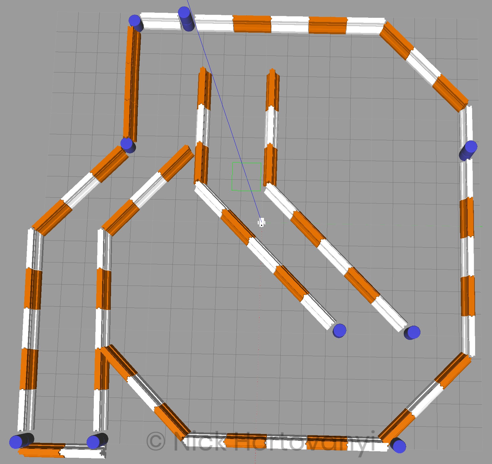
This project utilises Gazebo to create a simulation with a map provided by Clearpath Robotics
map

Once the robot has reached the navigation goal, the objective of the project has been achieved.

Background

A robot needs to understand where it is in a world, to be able to make navigation plans to get from point a, to point b, whilst avoiding obstacles. The process of understanding “where am I?” (from a robots perspective) is called localisation.

This project uses a localisation package built into ROS called Adaptive Monte Carlo Localisation (AMCL) to assist with the robot in a scenario to work out where it is. Hence the project name “Where am I?”.

AMCL is a variant of the Monte Carlo Localisation (MCL) which was learnt in the course material. MCL uses particles to localise the robot pose. It has several advantages over using Extended Kalman Filters (EKF) such as uses raw measurements (ie from lasers), is not reliant on gaussian noise, is memory and time efficient, and can perform global localisation.

The AMCL package adaptively alters the number of particles used, which has the advantage of reducing the computational overhead required.

Results

We first completed this exercise using the class room example which is named udacity_bot. Then a different version was created where the base and sensor locations were changed. This was named nick_bot and was launched using udacity_world_nick.launch.

The final results of when it reached the goal state follow.

udacity_bot

udacity_bot rviz
udacity_bot rviz

nick_bot

nick_bot rviz
nick_bot rviz

Model Configuration

This discussion is for the configuration of nick_bot.

The nick_bot was a square version of the rectangle based udacity_bot. The laser sensor was moved to the front of the robot.

The amcl_nick.lauch. Wherever possible the same configuration and parameters as the udacity_bot used amcl.launch.

min_particles was set to 25 and max_particles to 200 to not heavily utilise CPU. A higher max_particles did not improve initial ability of the robot to find itself with certainty.

odom_alpha1 to odom_alpha4 were trial & error values and changed from the default of 0.2 (there was not much documentation about).

The laser model parameters were left as default. There appeared no reason to change them as they were clearly visible on the above rviz visualisations and aligned to the barriers.

The yaw_goal_tolerance and xy_goal_tolerance were doubled from the default values to allow for additional flexibility in trajectory planning.

costmap_common_params_nick.yaml

transform_tolerance was set 1.25 and update_frequency to 3.0 for both local and global.

obstacle_range was set to 1.5, raytrace_range to 4.0 and inflation_radius to 0.65 to enable sufficient space on the cost map for the robot to navigate.

robot_radius was set to 0.4 in this model to allow for the larger square design.

local_costmap_params.yaml

The local publish_frequency was set to 3.0 with the global to 5.0 This configuration in conjunction with 15.0 x 15.0 sized local cost map was able to function within the performance constraints of the system used. Increasing the size of the local cost map utilise significant more computer power and missed the time windows for publish_frequency.

global_costmap_params.yaml

the update and publish frequency were set per above. In addition the width and height were set to the map size.

base_local_planner_params.yaml

sim_time was set to 4 as there appeared sufficient compute resource to estimate a trajectory out 4 seconds.

meter_scoring was enabled to ensure pdist_scale used meters.

pdist_scale was set to 0.5 being less than the default of 0.6. Default and higher values appeared to cause the robot to sometimes get stuck.

Discussion

The robot model was able to on most runs navigate successfully to the goal. The route taken at times could have been shortened. However further research is required into the ROS packages used to be able to tune it to achieve such. Often the observed path taken did not appear to be the most cost affective and when it missed the target goal, it would do a large sweep before re-approaching the target.

The AMCL routine appeared to quickly gain certainty about the locality of the robot. It was the rest of the navigation stack and move_base that needed further tuning.

In the kidnapped robot problem where by a robot is positioned in an arbitrary location, AMCL would be able to adapt the number of particles used to gain certainty of the robot’s location. In addition AMCL does not rely on landmarks, but on laser based maps, laser scans and transform messages to output pose estimates.

Moreover in an environment, where by there weren’t known landmarks, the AMCL has advantages over the Extended or Unscented Kalman Filter based approaches. These environments would include those with no known map (ie its the first time being navigated) or in highly unstructured environments with lots of moving structures over time eg shopping centres with popup shops in the aisles with significant foot traffic.

Future Work

The size of the local cost map had a significant impact on performance. Higher values decreased the ability to publish within the frequency required. In addition higher particle numbers whilst increasing CPU load did not reduce the time taken for the AMCL to be certain about the robots locality.

A square designed robot model as opposed to a rectangular design appeared to enable the robot to rotate more affectively around its base. Other wheel components are available but they did not publish ODOM information. Hence additional sensors might be required with further investigation into the impact of the removal of ODOM readings required.

A laser GPU gazebo component was available. This may enable reduced CPU load by moving the workload to the GPU.

A LIDAR unit would give a more complete map of the world around the robot. One could also look to include more laser sensors to map behind and to either side of the robot. This should facilitate with the creation of a more complete motion plan without the need for the robot to map it first.

When implementing this type of project on real hardware, the mobile nature of a robot, requiring it also to contain its own power sources, means that efficient usage of a CPU and GPU are a must. The higher the utilisation, the less effective time the robot will have to perform activities.

Thus whilst implementing more sensors may provide a more detailed and accurate map, in the field this would further drain the power source. Hence careful consideration is needed for the number of sensors, the total power consumption of the sensors and compute work loads, as well as the impact the quantity of data has to the compute utilisation rates whilst mobile.

If there no significant improvement in performance for the design objective and operational goals of the robot, then a more minimalist sensor and localisation cost map configuration may be appropriate.