Deep RL Arm Manipulation

This Deep Reinforcement Learning Arm Manipulation project has two objectives to achieve using a template project. Whereby to achieve each objective we create a DQN agent and define reward functions to teach a robotic arm.

The template project is based on the Nvidia open source project “jetson-reinforcement” developed by Dustin Franklin.

Robot Arm in Gazebo simulator

The two primary project objectives are:

  • Have any part of the robot arm touch the object of interest, with at least a 90% accuracy for a minimum of 100 runs.
  • Have only the gripper base of the robot arm touch the object, with at least a 80% accuracy for a minimum of 100 runs.

Written by Nick Hortovanyi

Reward functions

The reward functions are defined in ArmPlugin.cpp. The arm joints were updated using position control (as that was the programs default setting). For each joint there are two actions (either increase or decrease joint position).

REWARD_WIN was set to 0.125 (0.1 2nd objective) with REWARD_LOSS to -0.125 (-0.1 2nd objective).

If the robot gripper hit the ground a REWARD_LOSS * 10 was given and the episode ended.

Interim rewards, within the episode, were issued if there was no ground contact or 100 frames had beed exceeded.

The main interim reward was based on the distance goal delta between the gripper and the cycling prop. If a positive weighted average was derived then a REWARD_WIN was recorded otherwise REWARD_LOSS * distance to goal was issued. Thus the REWARD_LOSS was higher the further away from the goal the arm was.

For the gripper base (2nd) objective an additional REWARD_LOSS was added if the absolute average goal delta was < 0.001 to penalise no movement.

If the robot arm hit the prop, a REWARD_WIN * 10 was used for the first objective otherwise a REWARD_LOSS * 5 for the second objective if the collision was not with the gripper_middle.

However for the second objective a REWARD_WIN * 20 was issued if the collision point was gripper_middle.

Any collision ends the episode.
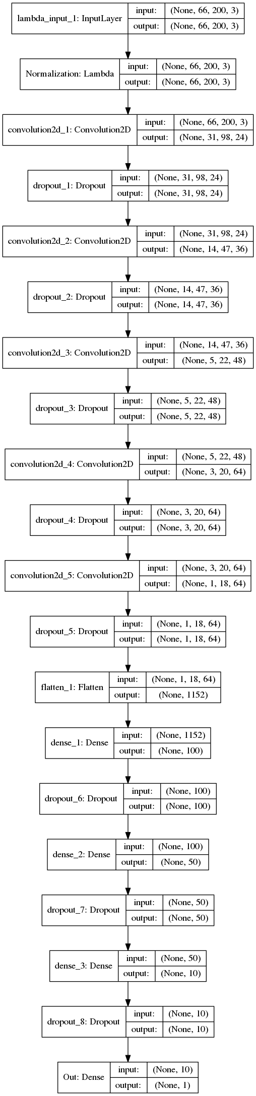
Hyper Parameters

Image dimensions were set to the same size as the input. Training was performed on a GTX1070 and there was no need to restrict memory usage.
INPUT_WIDTH 64
INPUT_HEIGHT 64

OPTIMIZER "Adam" was chosen as it in general performs better then RMSProp whilst maintaining its advantages.

For objective 1 the LEARNING_RATE was 0.1 with REPLAY_MEMORY at 1000. The value was chosen via trial and error.

For objective 2 the LEARNING_RATE was decreased to 0.01 due to the higher REPLAY_MEMORY set at 20000. The higher REPLAY_MEMORY was used so as to allow for more discrete learning, due to the smaller surface area required to achieve a collision to meet objectives.

For both BATCH_SIZE was set to 512 (again sufficient memory on the GTX 1070).

LSTM was used USE_LSTM true with LSTM_SIZE 256 which was set via trial and error.

Results

Objective 1 – Have any part of the robot arm touch the object of interest, with at least a 90% accuracy for a minimum of 100 runs.

Results objective 1
Results objective 1

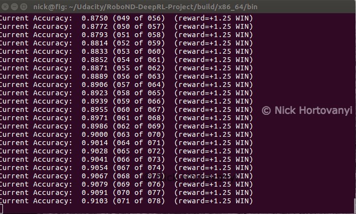
The robotic arm quickly learnt how to hit the prop with a degree accuracy in a repeatable fashion. On occasion if the arm trained initially away from the prop, it would take longer to achieve a higher accuracy.

Once a winning path was learnt this configuration consistently had the robotic arm quickly hitting the prop objective.

As can be seen in the above summary output the objective was achieved well within the criteria specified.

Objective 2 – Have only the gripper base of the robot arm touch the object, with at least a 80% accuracy for a minimum of 100 runs.

Results objective 2
Results objective 2

With the finer control required, and alteration to the interim reward system, this configuration would often hesitate before making a move. Whilst it learnt quickly how to get very close to having the gripper_middle hit the prop, it would also often just miss either hitting the ground or the arm itself hitting the prop. There seemed to be a repeatable pattern, of just extending past and swinging down in an arch, that once learnt gave consistent winning results.

Occasionally the middle joint would collide with the ground and this would lead to the objective not being met.

This configuration was not always reproducible, however with the above screen shot it was able to meet the objectives.

Future work

There were clear arcs that once found achieved a win quickly. Such that it would be worthwhile investigating an interim reward system based on not just the distance from the goal but also distance from an ideal arc trajectory as the arm approached.

Further using centre points to calculate distance from goals becomes less accurate the closer to the goal the arm is. Such that other points like the end of the gripper_middle and top of prop cylinder, would be worthwhile experimenting with.

Clone Driving Behaviour

Clone driving behaviour using Deep Learning

With this behaviour cloning project, we give steering & throttle instruction to a vehicle in a simulator based on receiving a centre camera image and telemetry data. The steering angle data is a prediction for a neural network model trained against data saved from track runs I performed.
simulator screen sot

The training of the neural net model, is achieved with driving behaviour data captured, in training mode, within the simulator itself. Additional preprocessing occurs as part of batch generation of data for the neural net training.

Model Architecture

I decided to as closely as possible use the Nvidia’s End to End Learning for Self-Driving Cars model. I diverged by passing cropped camera images as RGB, and not YUV, with adjusting brightness and by using the steering angle as is. I experimented with using 1/r (inverse turning radius) as input but found the values were too small (I also did not know the steering ratio and wheel base of the vehicle in the simulator).

Additional experimentation occurred with using comma.ai, Steering angle prediction model but the number of parameters was higher then the nvidia model and it worked off of full sized camera images. As training time was significantly higher, and initial iterations created an interesting off road driving experience in the simulator, I discontinued these endeavours.

The model represented here is my implementation of the nvidia model mentioned previously. It is coded in python using keras (with tensor flow) in model.py and returned from the build_nvidia_model method. The complete project is on github here Udacity Behaviour Cloning Project

Input

The input is 66x200xC with C = 3 RGB color channels.

Architecture

Layer 0: Normalisation to range -1, 1 (1./127.5 -1)

Layer 1: Convolution with strides=(2,2), valid padding, kernel 5×5 and output shape 31x98x24, with elu activation and dropout

Layer 2: Convolution with strides=(2,2), valid padding, kernel 5×5 and output shape 14x47x36, with elu activation and dropout

Layer 3: Convolution with strides=(2,2), valid padding, kernel 5×5 and output shape 5x22x48, with elu activation and dropout

Layer 4: Convolution with strides=(1,1), valid padding, kernel 3×3 and output shape 3x20x64, with elu activation and dropout

Layer 5: Convolution with strides=(1,1), valid padding, kernel 3×3 and output shape 1x18x64, with elu activation and dropout

flatten 1152 output

Layer 6: Fully Connected with 100 outputs and dropout

Layer 7: Fully Connected with 50 outputs and dropout

Layer 8: Fully Connected with 10 outputs and dropout

dropout was set aggressively on each layer at .25 to avoid overtraining

Output

Layer Fully Connected with 1 output value for the steering angle.

Visualisation

Keras output plot (not the nicest visuals)

Data preprocessing and Augmentation

The simulator captures data into a csv log file which references left, centre and right captured images within a sub directory. Telemetry data for steering, throttle, brake and speed is also contained in the log. Only steering was used in this project.

My initial investigation and analysis was performed in a Jupyter Notebook here.

Before being fed into the model, the images are cropped to 66×200 starting at height 60 with width centered – A sample video of a run cropped.

Cropped left, centre and right camera image

As seen in the following histogram a significant proportion of the data is for driving straight and its lopsided to left turns (being a negative steering angle is left) when using data generated following my conservative driving laps.
Steering Angle Histogram

The log file was preprocessed to remove contiguous rows with a history of >5 records, with a 0.0 steering angle. This was the only preprocessing done outside of the batch generators used in training (random rows are augmented/jittered for each batch at model training time).

A left, centre or right camera was selected randomly for each row, with .25 angle ( for left and – for right) applied to the steering.

Jittering was applied per Vivek Yadav’s post to augment data. Images were randomly transformed in the x range by 100 pixels and in the y range by 10 pixels with 0.4 per xpixel adjusted against the steering angle. Brightness via a HSV (V channel) transform (.25 a random number in range 0 to 1) was also performed.
jittered image

During batch generation, to compensate for the left turning, 50% of images were flipped (including reversing steering angle) if the absolute steering angle was > .1.

Finally images are cropped per above before being batched.

Model Training

Data was captured from the simulator. I drove conservatively around the track three times paying particular attention to the sharp right turn. I found connecting a PS3 controller allowed finer control then using the keyboard. At least once I waited till the last moment before taking the turn. This seems to have stopped the car ending up in the lake. Its also helped to overcome a symptom of the bias in the training data towards left turns. To further offset this risk, I validated the training using a test set I’d captured from the second track, which is a lot more windy.

Training sample captured of left, centre and right cameras cropped

Center camera has the steering angle and 1/r values displayed.

Validation sample captured of left, centre and right cameras cropped

Center camera has the steering angle and 1/r values displayed.

The Adam Optimizer was used with a mean squared error loss. A number of hyper-parameters were passed on the command line. The command I used looks such for a batch size of 500, 10 epochs (dropped out early if loss wasn’t improving), dropout at .25 with a training size of 50000 randomly augmented features with adjusted labels and 2000 random features & labels used for validation

python model.py --batch_size=500 --training_log_path=./data --validation_log_path=./datat2 --epochs 10 \
--training_size 50000 --validation_size 2000 --dropout .25

Model Testing

To meet requirements, and hence pass the assignment, the vehicle has to drive around the first track staying on the road and not going up on the curb.

The model trained (which is saved), is used again in testing. The simulator feeds you the centre camera image, along with steering and throttle telemetry. In response you have to return the new steering angle and throttle values. I hard coded the throttle to .35. The image was cropped, the same as for training, then fed into the model for prediction giving the steering angle.


steering_angle = float(model.predict(transformed_image_array, batch_size=1))
throttle = 0.35

Successful run track 1

Successful run track 1

Successful run track 2

Successful run track 2

note: the trained model I used for the track 1 run, is different to the one used to run the simulator in track 2. I found that the data I originally used to train a model to run both tracks, would occasionally meander on track 1 quite wildly. Thus used training data to make it more conservative to meet requirements for the projects.